Description
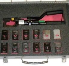
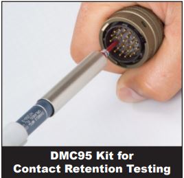
The quality assurance test most often overlooked is contact retention (the proper seating of contacts within the connector). This important test can now be performed simply and in a matter of seconds with the DMC95 Retention Test Tool Kit.
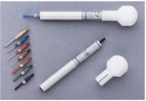
Tool kit supplied in 1 lockable steel case and includes: 6 Tool Bodies capable of testing from 1.5 to 40 pounds; 8 Pin Tips and 8 Socket tips sizes 8, 12, 16, 20, 22, 23, 24, & 26; Name Plate; Foam Pads/Inserts; Contents Charts; Instruction Charts; and Tool Selection Charts. These tools check the retention of pins and sockets in electrical connectors by indicating when proper pressure has been applied. Each tool body is set for a different poundage range (see Chart A on back of this page).
The tester tips are colour coded for specific sizes (AWG 8, 12, 16, 20, 22, 23, 24, & 26) and designated for pins or sockets (see Chart B). Use pin end tips to test sockets and socket end tips to test pins. All tips are made of aluminium and are replaceable. A nylon hand protector is provided with each tool body. The tools are adjustable and can be preset at the factory to your request.
Connector Series Serviced
MIL-C-5015 MIL-C-38999
MIL-C-24308 MIL-C-81511
MIL-C-26482 MIL-C-81659
MIL-C-26500 MIL-C-81703
MIL-C-28748 MIL-C-83723
Proprietary and other military connector series
may be serviced by DMC retention testers.
Please consult DMC for verification
HT250 ADJUSTABLE RETENTION TEST TOOL
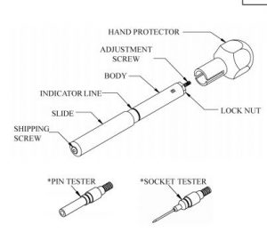
TOOL SET UP
1. Tool part number designates tool body only, without tip. Refer to Chart A for preset range of tool.
2. Remove button head (shipping) screw. Select appropriate tip and screw into tool body through slide.
Refer to Chart B for tip part numbers.
CHART A
Handle P/N* Range LBS.
HT250-1 1.5 THRU 3.0
HT250-2 3.2 THRU 5.5
HT250-3 4.0 THRU 8.0
HT250-4 7.0 THRU 18.0
HT250-5 17.0 THRU 25.0
HT250-6 24.0 THRU 40.0
CHART B – TIP PART NUMBERS
CONTACT SIZE COLOR CODE SOCKET TESTER PIN TESTER
8 RED 67-008-01 68-008-01
12 YELLOW 67-012-01 68-012-01
16 BLUE 67-016-01 68-016-01
20 RED 67-020-01 68-020-01
22, 22M, 22D COPPER 67-022-01 68-022-01
23 BLACK 67-023-01 68-023-01
24 GOLD 67-024-01 68-024-01
26 GREEN 67-026-01 68-026-01
USE OF TOOL
1. To test retention of socket contacts, use socket tester tip with preset tool. Insert tester (pin) into mating end of contact. Tool must be in a straight line with contact. For pin contacts, fit pin tester to tool body and place over contact at the mating end.
2. Apply pressure toward contact until slide aligns with indicator mark, contact should remain firmly in place.
TOOL ADJUSTMENT
1. Remove hand protector, back off lock nut away from body of tool to allow free movement of adjustment screw.
2. Secure tool in RTCG-75 or equivalent setting gage forprecise calibration. If precise calibration isn?t required, you can set the tool by holding the tool firmly by hand on a scale or other weight indicating device, and apply axial force until the end of the slide is aligned with the indicator mark. Note reading of force on gage (or accurate weightscale).
3. Adjust tool to required force by turning adjustment screw with a screwdriver, clockwise to increase force and counterclockwise to decrease force. When required value is achieved, tighten lock nut firmly while maintaining alignment of slide and indicator line. Tool is now set.
4. Note: Inspection stickers may be used to seal hand protector onto tool body, in order to signal any tampering with the adjustment screw